
There was a VPN issue to troubleshoot recently. It was between Juniper SRX and Cisco Router. It seems straightforward but it took quite a long time to troubleshoot because of communication. All steps listed here for my future reference.
Some other related posts:

1. Enabled Debugging on Cisco IOS Router
Some other related posts:
- Troubleshooting Cisco IPSec Site to Site VPN - "reason: Unknown delete reason!" after Phase 1 Completed
- Troubleshooting Cisco IPSec Site to Site VPN - "IPSec policy invalidated proposal with error 32"
- Troubleshooting Cisco IPSec Site to Site VPN - "QM Rejected"
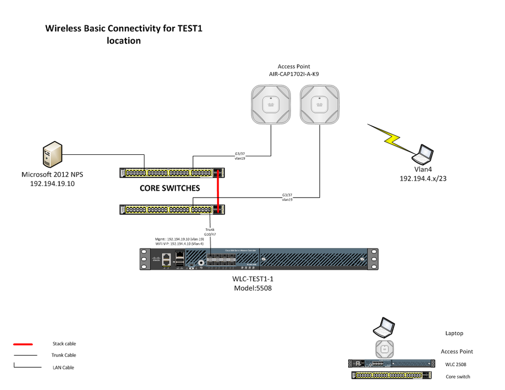
Diagram
1. Enabled Debugging on Cisco IOS Router
vpn-R1#debug crypto ipsec
Crypto IPSEC debugging is on
vpn-R1#debug crypto isakmp
Crypto ISAKMP debugging is on

vpn-R1#debug crypto engine
Crypto Engine debugging is on

vpn-R1#terminal monitor


 RSS Feed
