
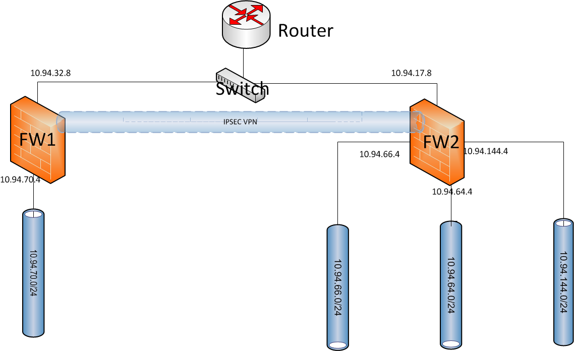
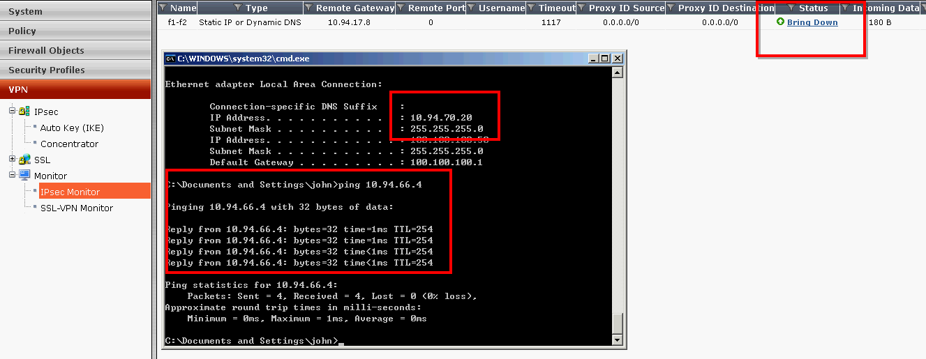
The Fortigate 60D and 100D were used to build IPSec tunnel between two sites since last year. The Firmware version is 5.2.4 build 668. I were planning to upgrade Fortigate 100D to 5.4.1. The upgrade process were smooth but IPsec tunnel got broken after upgrade.
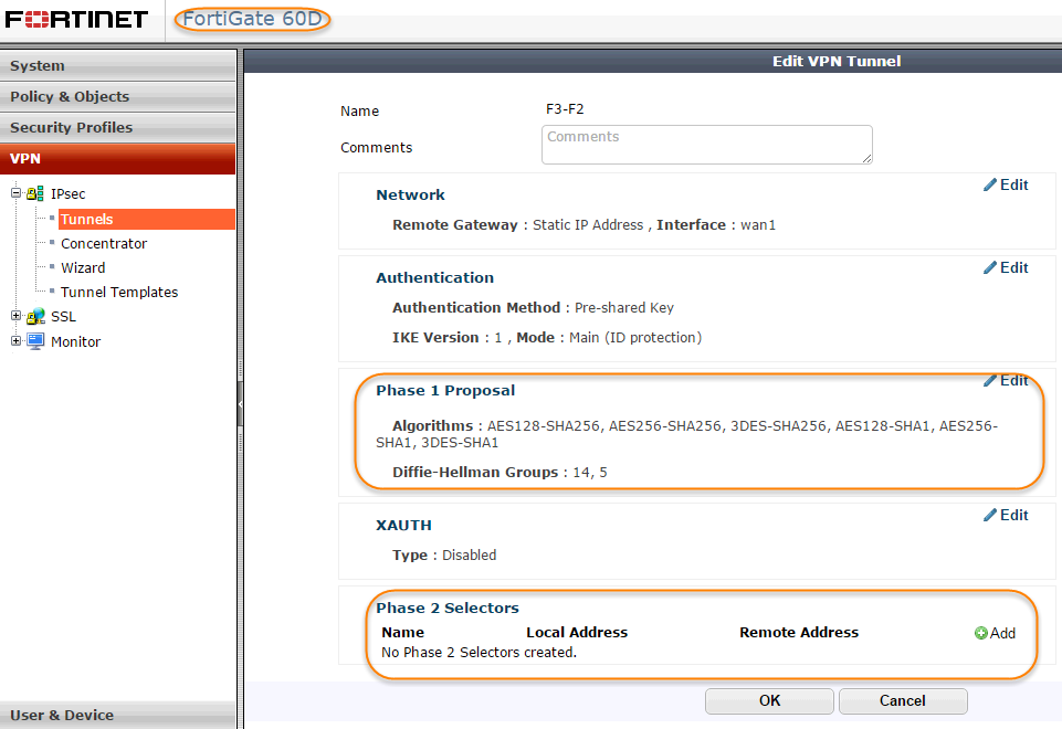
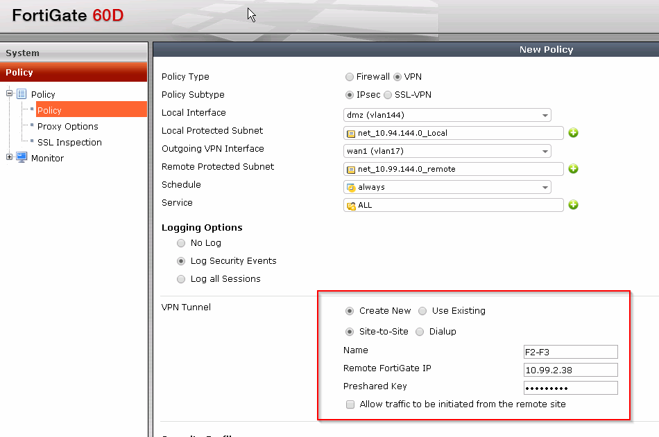
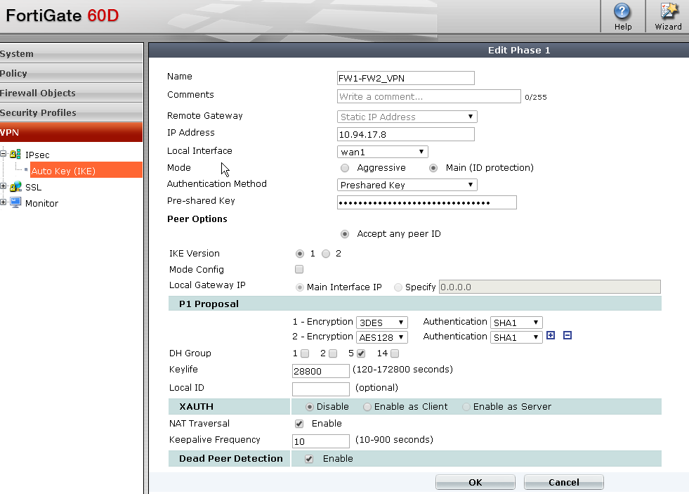
Fortigate60D IPSec Tunnel Configuration:
Fortigate100D I{Sec Tunnel Configuration:
Fortigate60D IPSec Tunnel Configuration:
Fortigate100D I{Sec Tunnel Configuration:


 RSS Feed
